Multi-size Products Specification
- Former user (Deleted)
- Marco Peters
- Nicolas Ducoin (Unlicensed)
Goals
- Other than BEAM, SNAP's product data model should be able to deal with products that have bands of different image sizes and geo-codings
- There shall be one model coordinate reference system for the whole product.
- Users of the API shall be able to use all SNAP functionality for both single-size and multi-size products.
Findings of meeting from October 1st, 2015
This meeting took place after we ran into several problems resulting from the implemented changes described below. We found that the approach using SceneRasterTransforms was misguided, as it existed alongside the already present transformations between reference systems within SNAP.
We identified a need to exactly define the meanings of the various coordinate reference systems in SNAP. This becomes the more important as this concept needs to be adapted to consider bands of different sizes within the same product. At the core, it stands that there needs to be a single model crs for a product. Images provide imageToModelTransforms which transform from the respective image crs' onto the model crs'. Also, all vector data is saved within model coordinates. What is the model crs depends on the used geocoding. If a CrsGeocoding is used, there is a map crs which will be the model crs. In other Geocodings, there is no map crs (or, strictly, the geo crs will fill that role) and the model crs should be the image crs. In multi-size products, as there are multiple images it is not clear what is the image crs which shall constitute as the model crs.
Also, as there are multiple images, it makes less sense for a product to provide such things as a scenerastersize or a geocoding, as these are not necessarily valid for the whole product anymore. However, for single-size products, these values can still be provided as they still make sense.
There are a lot of places within the SNAP code where the scenerastersize or the product's geocoding are requested. In these cases, the product can return the common rastersizes. If these are null, either the operation shall not be performed or the band- / rasterdatanode-specific sizes or geocodings should be used.
A major obstacle here is that there are numerous places where a careful code revision is required. Also, unexpected problems might still occur.
The big remaining question is whether the adaption of the existing image crs/geo crs/model crs - concept to multi-size images along with band-oriented raster sizes and geocodings is feasible.
Background and strategic fit
Raster data (“bands”) may be of different pixel resolution and/or are related to different coordinate systems. BEAM’s strategy is to upscale all bands with lower resolution to the highest one. This causes several problems in the toolbox and it’s APIs:
- Data explosion on disk when writing products
- Redundant computation of duplicated pixels (band maths, geometric operations)
Keeping all bands in their native resolution would cause the following problems:
- GPF tile processing is not defined anymore: what’s a tile then?
- Image display at native resolutions complicates visual comparison
- Band math cannot deal with that at all, as all pixels must be collocated
BEAM has some basic support for multi-resolutions / different geo-codings per band:
- Product.getSceneRasterWidth () and RasterDataNode.getSceneRasterWidth() vs. RasterDataNode.getRasterWidth()
- Product.getGeoCoding() vs. RasterDataNode.getGeoCoding()
Requirements
| # | Title | User Story | Importance | Notes |
|---|---|---|---|---|
| 1 | SMOS | No source raster data, grid-points | Essential | In the SMOS-Box, we transform and resample them to a lat/lon coordinate system, resolution is determined such that each grid point is represented by 6x6 pixels |
| 2 | Tie-point grids | Regular sub-sampled scene raster grid. May or may not be scaled/resampled in image views. | Essential | In the BEAM data model, tie point grids are scaled up to scene resolution, bi-linear interpolation resampling |
| 3 | Landsat 8 | The panchromatic band has a resolution of 15m, while the other bands have 30m; | Essential | In the BEAM reader, all bands are scaled up to 15m, nearest neighbour resampling, no interpolation |
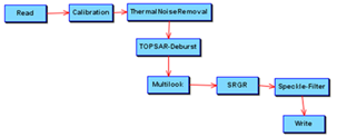
| 4 | S-1 L1 SLC | Sentinel-1 IW and EW SLC products have 3 to 5 sub swaths with each sub-swath as a band with its own dimensions and geocoding.
Swath1 Swath2 Swath3 GPF processing must be able to work on each band independently. For example, a typical graph would be to transform the level-1a SLC to a level-1b GRD.
In this case, the TOPSAR-Deburst operator joins the bursts (each block separated by no data) and merges the sub-swaths. After the deburst operator, the target product is as usual with one dimension for all bands and the same geocoding for the whole product. Before deburst, the calibration operator must deal with each band independently with their own dimensions and geocoding. | Essential | - |
| 5 | S-2 MSI L1C / L2A | The bands are provided in 10m/20m/60 resolutions. Image view shall display the images in their original resolution (no default scaling/resampling). | Essential | In the SUHET reader, all bands are scaled up to 10m, nearest neighbour resampling, no interpolation. |
| 6 | S-3 SLSTR L1B | The data is provided in 500m and 1km, in oblique and nadir views which cover different spatial extents. Image view shall display the images in their original resolution (no default scaling/resampling). | Essential | In the SUHET reader, all bands are scaled up to a 500m nearest neighbour resampling which covers all area covered by at least one band, no interpolation. Area which is part of the product but not of a band is marked as no data. |
| 7 | Quicklooks | Assuming we save quicklooks with the product, the product should have a new type of raster for quicklooks. The quicklooks should be a separate list from bands. Quicklooks are a reduced resolution representation of the product. There may be several types of quicklooks including RGBs, decompositions, and map projected. However, this introduces another problem regarding the number of bands in terms of channels within the image that currently holds the data of a band in terms of a product. | Desired | - |
| 8 | Hypothetical action “New Product” | Thinking about this non-existent but still useful action shall help understanding the issue of having products that support multiple raster data resolutions:
| Optional | - |
| 9 | AVHRR/AATSR | For AVHRR (cropped) and AATSR (flipped) the data read from the file is changed. While all bands have the same resolution, the pixel coordinate system changes. This makes problems when it comes to match-up analysis. The pixel positions don't match the pixel position in other software. This makes it difficult for the user to compare results. | Desired | The transformation can consider the cropping and the flipping. Additionally the native raster pixel location need to be supported in the UI and in the various pixel export tools. |
| 10 | Real User | Product comes in multiple resolution the user wants to select the one of the present resolutions to work with. | Desired | One of the possible solutions might be incompatible with other requirements. |
User interaction and design
General Approach
There are basically two approaches to deal with multi-size bands in the BEAM data model. The first one would be to let ProductReaders return multiple Product instances. For example, the S-2 MSI reader could return three products, one for each of the 10, 20, and 60 m bands. This way no spatial rescaling would be needed at ProductReader level, and the constraint to have a single image resolution within one Product instance would be retained. The second approach is to let the BEAM data model deal with multiple resolutions directly.
The disadvantage of the first approach is that it is very unhandy for implementors of GPF Operators. They have to deal with multiple source products at different resolutions. For a given target tile, how are source tiles computed? Also many visual tools in BEAM (e.g. spectrum toolwindow, spectral unmixing, magic wand) would need to be rewritten in order to account for the fact, that a spectrum is now distributed over a number of open products.
Therefore we propose to implement the second option – extending the BEAM data model to correctly handle multi-size bands.
Transformations Approach
This approach is based on the assumption that SNAP already provides everything required to support multi-size products, as there is already a system of image, model, map,and geographic coordinate reference systems (crs's). In single-size products, there is at least an image crs span by the product's scenerastersize. In most cases, there is also a geographic crs, which relates the pixels to a geographic spatial extent and location. Projected products in addition have a map crs which describes how the geographic coordinates are projected onto a surface. The model crs, finally, can be understood as the common product crs. Vector data is stored and exported in model coordinates and there exists an affine transformation between the image crs and the model crs. If a map crs is provided, it also poses as model crs (so there is an affine transformation between the image crs and the map crs). If there is no dedicated map crs, the image crs serves as the model crs, as there is not necessarily an affine transformation between the image crs and the geo crs.
In multi-size products, there are by definition multiple image crs's. Still, there should be only one model crs. When a map crs is provided, it shall serve as the model crs <- Here we make the assumption that a map crs is universal across the product. If there is no map crs, there must be an image crs which is assigned as the model crs. There is not a need that this image crs is actually employed by one of the actual bands.
Former Approaches
SceneImageTransform Approach
The basic idea is to equip the Product class with something we call a scene image geometry, which refers to the spatial collocation of all the native image geometries of the Product’s Bands where
Image Geometry = Pixel Resolution + Tiling + GeoCoding .
Product class
Existing properties for the scene image geometry of the Product class:
- geoCoding: GeoCoding (will be deprecated, use a sceneGeoCoding instead)
- sceneRasterWidth: int
- sceneRasterHeight: int
New properties for the scene image geometry of the Product class:
- sceneRasterTileWidth: int
- sceneRasterTileHeight: int
- sceneRasterSize: Dimension
- sceneRasterTileSize: Dimension
RasterDataNode class
Existing properties for the native image geometry of the RasterDataNode class:
- geocoding: GeoCoding
- rasterWidth: int
- rasterHeight: int
- sceneRasterWidth: int (= Product. sceneRasterWidth, deprecate?)
- sceneRasterHeight:int (= Product. sceneRasterHeight, deprecate?)
New properties for the scene image geometry of the RasterDataNode class:
- rasterSize: Dimension
- rasterTileWidth: int
- rasterTileHeight: int
- rasterTileSize: Dimension
- sceneImageTransform: SceneImageTransform
The value of RasterDataNode.sceneImageTransform allows a Band’s native raster data to be spatially transformed into the product’s scene image geometry and vice versa. It comprises a forward and inverse pixel coordinate transformation:
public interface SceneImageTransform {
    SceneImageTransform IDENT = ...;
    org.opengis.referencing.operation.MathTransform2D getForward();
    org.opengis.referencing.operation.MathTransform2D getInverse();
}
Note that it is legal to have SceneImageTransform instances whose either forward or inverse (but not both) pixel coordinate transformations are not available. ImageTransform instances may be explictely set (e.g. by ProductReader/Operator instances) on a RasterDataNode, or computed using both the Product's and the RasterDataNode's GeoCodings. The computation might not be possible at all or fail, in which case RasterDataNode.imageTransform does not exists. In (Python) pseudo code:
def getSceneImageTransform():
	if self.sceneImageTransform:
	    return self.sceneImageTransform
    else:
        return self.computeSceneImageTransform()

def computeSceneImageTransform():
	r = self
	p = self.product
    if r.geoCoding and not p.geoCoding:
        throw IllegalStateException('raster geo-coding found, but product geo-coding is undefined')
    if r.geoCoding == p.geoCoding and r.rasterSize == p.sceneRasterSize:
        return SceneImageTransform.IDENT
    ...
    return None
The SceneImageTransform shall allow to convert any pixel coordinate of a RasterDataNode's image CS into a pixel coordinate in the Product's image CS and vice versa. It must be used whenever vector data is displayed or interacted with in a ProductSceneView, because vector data uses the Product's image CS coordinates. For example, we can only add new vector data features (e.g. pins) to a displayed band if it is possible to convert the displayed band's pixel coordinates into pixel coordinates of the Product image CS. With other words, the band's SceneImageTransform must exists and have a valid inverse transform.
In accordance to methods getSceneRasterWidth and getSceneRasterHeight, the class RasterDataNode can provide further methods which operate on either a pixel in product or in band coordinates.
The current class hierarchy of RasterDataNodes can stay as it is right now.
ImageGeometry approach
Note: The following approach has been deprecated in favor of the SceneRasterTransform approach outlined above.
Currently, there is already a class named 'ImageGeometry'. It's main purpose is to store and compute the target image geometry (GeoCoding and resolution) for reprojection. To be able to use the interface name 'ImageGeometry' the existing class will be renamed to 'ReprojectionImageGeometry'. It should be possible to replace this class by the new implementation of the 'ImageGeometry' interface:
public interface ImageGeometry {
    int getWidth();
    int getHeight();
    int getTileWidth();
    int getTileHeight();
    Dimension getSize();
    Dimension getTileSize();
    GeoCoding getGeoCoding();
}

public interface ImageGeometryTransform {
    RenderedImage transform(RenderedImage source,
                            GeoCoding sourceGeoCoding,
                            ImageGeometry targetGeometry);
}
Possible operations used during spatial up-/down sampling: scale, crop, border-extend. By default, if no special transform is given per band, the scene image geometry is computed as follows:
TBD
GPF API Changes
At this point in time (SNAP 2.0, May 2015), we don’t want to change the GPF API at all. This means, GPF operators will always be asked to compute tiles defined in the scene image geometry of the target product. Required spatial transformations will be performed transparently. It is also important to retain all raster data accessors that can be used to retrieve the native raster data using the native raster data pixel coordinate system. This way, a GPF operator can operate on native source raster while providing target data in scene image geometry.
Issues
- Layers need to be placed on bands of all sizes. When the band size differs from the product size, the layer must be transformed.
- For multilevel-images, it must be considered that images from different bands might use different scalings
Use Cases
This table lists use cases which might prove problematic when dealing with bands of different sizes.
| No. | Use Case | Option 1: Very restrictive | Option 2: Transform to product grid (B<i>.CS -> P.CS) | Option 3: Transform to product grid to raster grid (B<i>.CS -> P.CS -> Bh.CS) |
|---|---|---|---|---|
| 1 | Band Arithmetic: Combining two or more bands of different sizes (adding, multiplying, ...) to create a new band / Creating a RGB Image View from multi-size bands | Don’t allow it, display error message ((/) done in Maybe extend Symbol with method Problem: must provide to users an operation that does the transform from B<i>.CS -> P.CS | Auto-transform to product resolution B<i>.CS -> P.CS Problem: Might not be expected by users | Auto-transform to Bh res which has the highest res of the B<i>
Problem: we need to find and perform transform B<i>.CS -> P.CS -> Bh.CS |
| 2 | Correlative Plot/Profile Plot: Displaying a plot for a rdn with vector data | The position of the vector data within the raster image coordinates is considered. Parts of the geometry outside of the image will not be displayed in the plot. When the box size value is altered, it will refer to the pixel size of the raster image grid. Only compatible (equal size) ROI Masks are selectable. | The position of the vector data within the raster image coordinates is considered. Parts of the geometry outside of the image will not be displayed in the plot. When the box size value is altered, it will refer to the pixel size of the raster image grid. | The position of the vector data within the raster image coordinates is considered. Parts of the geometry outside of the image will not be displayed in the plot. When the box size value is altered, it will refer to the pixel size of the raster image grid. |
| 3 | Adding/Managing GCPs or Pins | GCPs and Pins will be displayed in all rdn's of a product. They will be displayed at the location which is specific to the grid. When the pin/GCP is moved, its position will change in all product scene views. Pins or GCPs are always located at the center of a pixel. | GCPs and Pins will be displayed in all rdn's of a product. They will be displayed at the location which is specific to the grid. When the pin/GCP is moved, its position will change in all product scene views. Pins or GCPs are always located at the center of a pixel. | GCPs and Pins will be displayed in all rdn's of a product. They will be displayed at the location which is specific to the grid. When the pin/GCP is moved, its position will change in all product scene views. Pins or GCPs are always located at the center of a pixel. |
| 4 | Placemark/GCP view | In the views, the pixel position is given in product coordinates. This is noted explicitly. | In the views, the pixel position is given in product coordinates. This is noted explicitly. | In the views, the pixel position is given in product coordinates. This is noted explicitly. |
| 5 | GeoCoding | The GeoCoding information will be displayed for the currently selected rdn. | The GeoCoding information will be displayed for the currently selected rdn. | The GeoCoding information will be displayed for the currently selected rdn. |
| 6 | Layer Manager | Only allow adding bands B<i> where B<i>.CS == Bv.CS | Auto-transform all bands to Prod res.To transform a grid onto another grid, the user can choose which type of interpolation to use. By default, NEAREST NEIGHBOR is selected. Problem: Might not be expected by users | Auto-transform all bands to Bv res. To transform a grid onto another grid, the user can choose which type of interpolation to use. By default, NEAREST NEIGHBOR is selected. Problem: we need to find and perform transform B<i>.CS -> P.CS -> Bv.CS |
| 7 | Mask Manager | Masks are only displayed/applicable to bands of the same size/resolution. It is not allowed to combine rasters of different sizes to create a new mask. | Both the grid and the mask are transformed to the product grid. Problem: Might not be expected by users | The grid in the currently selected productsceneview sets the reference grid: A mask will be displayed with regard to this grid. The mask is interpolated onto a grid using the NEAREST NEIGHBOUR method. Problem: we need to find and perform transform B<i>.CS -> P.CS -> Bv.CS |
| 8 | Navigation | When clicking 'Zoom to all', the zoom will be performed with regard to the rdn bounds. When the "Synchronizing" options are selected, the synchronistion should behave like for multiple products right now.. | ? | When clicking 'Zoom to all', the zoom will be performed with regard to the raster bounds, not the product bounds. When the "Synchronizing" options are selected, the viewports and the cursor position will be transformed, such that not the same pixel locations are used. |
| 9 | Pixel Info View | Only display pixel values of bands B<i> where B<i>.CS == Bv.CS If Bv.CS != P.CS don't show scan line time. If Bv.CS != P.CS don't show TPGs. If TPG shown don't show Bands != P.CS | ? | Display pixel values of all bands B<i> at corresponding pixel positions given by Question: Shall an interpolation be used? |
| 10 | Scatter Plot | Only show scatter plot for bands of the same size. Error is already shown but selection should be prevented. | Transform both bands to product coordinates. | Scatter plots can be shown for bands of all sizes. The number of pixels will be determined by the grid with more pixels. If for one pixel no corresponding pixel exists in the other band, it will not be considered in the plot. |
| 11 | Spectrum View / Magic Wand Tool | Only display pixel values of bands B<i> where B<i>.CS == Bv.CS | Transform all concerned bands to product coordinates. Display pixel values of all bands B<i> at corresponding pixel positions given by Bv.CS -> P.CS | Display pixel values of all bands B<i> at corresponding pixel positions given by Bv.CS -> P.CS -> B<i>.CS |
| 12 | Non-UI operations using masks | Masks will only be applicable to bands of the same size. | Masks and bands will be scaled to be on the product CS. | The mask will be transformed to be on grid of the concerned raster data node (or, in the case of multiple raster data nodes with different sizes, of the one with the finest resolution). |
| 13 | World Map | The World Map will display the bounds of products. | The World Map will display the bounds of products. There is an option to display bounds of raster data nodes of a different grid, too, in a way it is apparent they are part of the product. | The World Map will display the bounds of products. There is an option to display bounds of raster data nodes of a different grid, too, in a way it is apparent they are part of the product. |
| 14 | Create Filtered Band | Option will only be available for bands on the product CS. | Box sizes will refer to pixel sizes of the product CS. | Box sizes will refer to pixel sizes of the selected raster CS. |
| 15 | Create Geo-Coding Displacement Bands | These bands can be only created for the product geo-coding. | These bands can be created for geo codings of bands, too, if these might differ from the product's geocoding. | These bands can be created for geo codings of bands, too, if these might differ from the product's geocoding. |
| 16 | Attach Pixel Geo-Coding | Pixel Geo-Codings can only be attached to the whole product. | Pixel Geo-Codings can be attached to either the whole product or single bands. The latitude/longitude bands must be of the same grid as the product/band(s) for which they are created. | Pixel Geo-Codings can be attached to either the whole product or single bands. The latitude/longitude bands must be of the same grid as the product/band(s) for which they are created. |
| 17 | Compute Mask Area | The mask must have the same CS as the product or its own GeoCoding. | The mask area will be computed with regard to the product CS. | The mask area will be computed with regard to the raster in the currently selected product scene view. |
| 18 | Pixel Extraction | This operation will only be available for raster data nodes on the product grid. | Bands will be transformed onto the product CS. Pixel windows refer to pixel areas in the product CS.
| Pixels to be considered for extraction are determined on base of geographic coordinates, i.e., exactly one pixel can be determined. As no reference grid can be determined, for each pixel the window size is given in the pixel sizes of the grid: A 3x3 window is always a 3x3 window, regardless of the area covered by the pixels in the respective grid. |
| 19 | GPF: Use of PixelOperators | Only bands on the product grid can be considered. | Bands will be transformed onto the product CS, if necessary. | A PixelOperator operating on multi-sized source rasters will provide the option to either collect source samples on a pixel basis (no transformation) or on a location-aware basis (using scene raster transformations). The method computePixel will be passed sourcesamples accordingly. The option will not be public. When using computeTileStack, each pixel will be either transformed or non-transformed, depending on the option set. By default, the option will be set to "transform". The source resolution of the output bands will be determined as in use case 1. |
| 20 | Reprojection / Orthorectification | Don’t allow it, display error message
Problem: must provide to users an operation that does the transform from B<i>.CS -> P.CS | Auto-transform all bands to product resolution B<i>.CS -> P.CS Problem: low res bands are exploded to highest res, redundant info, more memory | n.a. |
| 21 | Subset / Flipping | Don’t allow it, display error message
Problem: must provide to users an operation that does the transform from B<i>.CS -> P.CS | Auto-transform all bands to product resolution B<i>.CS -> P.CS Problem: low res bands are exploded to highest res, redundant info, more memory | n.a. |
| 22 | Binning | Only allow binning for bands on a product CS. | Transform all bands to product CS. | When using expressions, proceed as for Band Maths. Use grids in their native sizes. |
| 23 | Mosaicing | Only allow for bands on product CS. | Transform all bands to product CS. | When using expressions, proceed as for Band Maths. Use grids in their native sizes. |
| 24 | Collocation | Don’t allow it, display error message
Problem: must provide to users an operation that does the transform from B<i>.CS -> P.CS | Auto-transform all bands to product resolution B<i>.CS -> P.CS Problem: low res bands are exploded to highest res, redundant info, more memory | This is the one tool where different CS are actually dissolved: All bands are transformed to the CS of the master product.
Comment: This tool might be enhanced, such that bands can be transformed onto a product grid for good. |
| 25 | Range Finder | Only allow for rasterdatenodes with product resolution | Use band CS to determine range | Use band CS to determine range |
| 26 | Graticule Layer | Display correct graticule for each displayed rasterdatanode. | Display correct graticule for each displayed rasterdatanode. | Display correct graticule for each displayed rasterdatanode. |
Questions
Below is a list of questions to be addressed as a result of this requirements document:
| Question | Outcome |
|---|---|
| How can we make sure that GPF can compute multi-size products without scaling/resampling them to scene geometry? | Make Operator.computeTile() ask clients to compute a target band's native raster instead of the product's scene raster. TBD! |
| How will the ReprojectionOp do its job for multi-size products? Always output scene geometry or reprojecting each band independently? | Output scene geometry for time being. Reprojecting each band independently requires band-independent parametrisation. |
Note that a band’s validMask must also be rescaled --> fuzzy confidence mask? |
|
| How are raster data node tiles defined when the node data only covers a subset of the product's spatial extent? |
Not Doing
- We wont change the product reader interface so that it can read multiple products (as indicated in section "General Approach" above)
Decision
- We go for the 'Option 1: Very restrictive' in the above Use Cases table.
- For products which contain raster data in multiple resolutions, there should be one plugin for each resolution
- All can return intended as the decode qualification
- The ReadOp will be extended with a format name parameter, when doing this we can also change the file parameter to a string or to an URI.
- When a product is opened in SNAP the user will be asked which of the intended product readers shall be used (also suitable reader are shown ans selectable). The user decision can be stored.
- In the Band Maths when the expression is parsed a parse exception is thrown if the used rasters are not compatible.